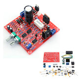
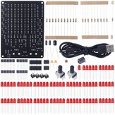
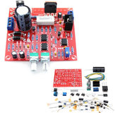
0-30V 2mA - 3A Adjustable DC Regulated Power Supply Module DIY Kit
US$4.99
A part of the review has been auto-translated.
ordered 3 of these cheap pcb's, all workt perfect after a few hours of soldering. Now the main test: the transformer is a 24v ac 90 watt the load is a 10R / 50 watt resistor, I put voltage to 20Volt that's 2amps, all 3 blew up after some while...3x the 2sd1047 broke down, after replacing the 1047 on 1 of the pcb's and again testing 2 of the tl081 blew up... After checking the schematic I see that the tl081 gets almost 30 volt and -5 at power pins, that is nearby max of ic...So I changed this, now the tl081 gets +5 and -5 at power pins... next change put 2 1047 in parralel with an extra resistor 0.33R in the emitter line....all works perfect now, but watch out, if you going to use 3 amps out of this power supply this is near the max of used parts, it can get you into some nice firework, so don't go over 2.5 amps.....Than another nice mod. take out the parts that make the -5 volt that fed the tl081's, than use a 7805 and a ltc660 (or similar) and fed the 081's with the -power with the mod. Now you can also use a dc powersupply for fed this pcb....And make sure you cool the 2sd1047, I use an old 478 + fan intel cpu cooler.... It's a fun project to build, has some flaws but can easily be fixed...

The kit is really excellent.I made a variable bench power supply by using this kit.The detail project is on Instructables https://www.instructables.com/id/DIY-Bench-Power-Supply/ https://youtu.be/p50oae_Nnq0

Nice DIY kit, experienced person can assembly without the manual. Pros: -Easy to assembly -Cheap -Constant current mode Cons: -After about 45 minutes of continuos use, the voltage regulator (7824) get too hot and trigger its internal overtemp protection, you will see the output decrease quickly. This can be solved adding a heat sink on 7805 IC (so cheap that could be included) -There is no short circuit protection, if you accidentally short the output, Q2 (2SD882) will burn. (It's a common NPN low power transistor, can be replaced by BD135, BD139). Add a fuseor a resetable fuse to avoid it. I recommend it, even having some flaws.
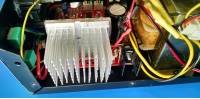
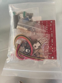
First I would suggest you shall not complain for missing heat sink, fan and transformer. Only the transformer will be almost double the price of the electronics and the weight of the package will make it more expensive to ship. Parts were all in the antistatic bag and documentation can be downloaded. Depending on your skills can take from 1 to few hours until you open the bag until you are ready to test. Once everything has been assembled the PS shall work and do what it says will do. There are few things that you shall pay attention: 1. AC transformer that delivers more than 24V ac when not under load. If that is the case most likely you'll blow two TL081 op amps that are powered between the output of the main rectifier and the supplementary -5V source (U2 and U3). 2. AC voltage shall not drop under 24V fi you want to get 30V at the output and even then only for lower output currents. 3. Potentiometers supplied are very hard to precisely adjust. 4. R3, 220 Ohms, gets quite hot. My recommendations are: A. Forget about 30V output at 3A, settle for 24V or less B. Get a decent AC transformer that can deliver 22V with no load and 21V at 3A for 24V out. C. Get a nice CPU heat sink without fan and install D1047 on it with a little thermal grease. Install the transistor remote, such as the heat sink is in the open and the fins are vertical to allow proper air flow. D. Forget about 3A continuous and aim for 2A. You can still have 3A for short periods of time, but that will overheat the rectifying diodes and the ripple out of the filter capacitor will be too high. E. Spend more money if you want a real 30V/3A continuous duty PS, but for the $10 you paid be happy with what you've got, a very decent, regulated PS that can be used in your own home lab and which you put together yourself.
Very lovely, school grade design, simple to assemble, fine operation, bought two of them. However, technical specification for max voltage should be lower. When I connected it to 24V AC transformer one operational amplifier burnt practically immediately. After reviewing schematics, it was quickly clear. Op amp TL081 is specified at +-18V max power supply (36V). In this design, power supply voltage for two out of three op amps is 39V, vhen connected to 24V AC transformer. (-5V + sqrt(2)*24V ). It should use different configuration for op amp supply or op amps with higher voltage (ex. OPA604A). Latter was my solution, since I have pair of 24V transformers. But as I said, lovely little kit.
Orderd it because of the really low Price, I have allready some bench power supply's at home, but you can never have enough. Soldering was quiet easy, cant belive getting so good kit's at this low / reassonable price. All Parts are included except the heatsink / fan for the power transistor. I like the kit and good that I orderd two of it maybe I will give one away.

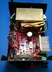
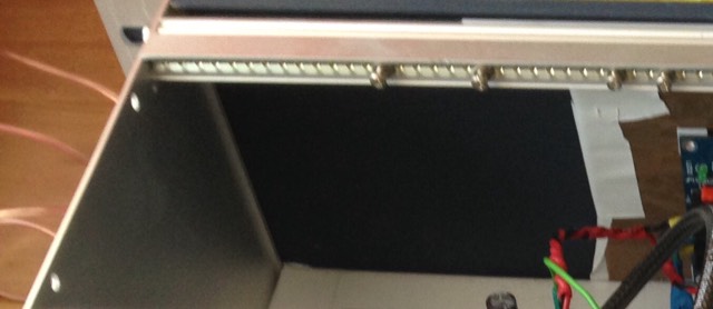
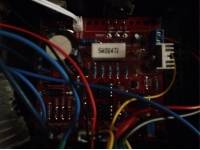
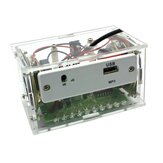
Initially it failed to work once assembled. I found that one of the 1n4148 diodes was bad. This caused it to only give a fraction of a volt, and I am fairly sure it would have burned the opamps especially U2 if I hadn't noticed it was quickly getting hot. I am unsure if the diode came in defective, or failed after installing it, as I did not test it before installing it. I happened to have some so I replaced it, and the powersupply worked after that. I am powering it by a 12volt transformer, which gave an output about 19volts without a load (it would not be able to maintain that with a load). The opamps are said to at best marginally handle the 24volt transformer that is suggested, I didn't need anywhere near 30 volts output, so I went with a 12volt transformer I had, being 12volts is the most I will need for anything I am looking to use this for. I added a resistor to the voltage adjustment pot P1 to limit the top voltage to around 15volts, by narrowing the range it gives finer control of the voltage without adding an expensive 10turn pot.. The most voltage I need is basically 12volts, so I may lower it more for finer control, or add a second pot for fine tuning. I switched out the 7824 for a 7812(with a small heatsink) and used a 12 volt fan blowing down across a reasonably large aluminum heatsink, and added in a lcd meter powered by the 12volt regulator as well (with a flyback diode on the regulator output due to the fan as well, it can be seen on the second picture wired into the power going to the fan). For some reason the minimum current was much higher than the 2mA listed, more like 82mA as is shown in the one picture. I don't know if the 82mA has anything to due with the lower input voltage from the transformer or not. I have worked it down to about 20mA by reducing R17 (the 33ohm resistor). I will probably adjust R18 to limit the current like I did with the voltage for finer control, as I don't need 3Amps (although I may make it adjustable, just in case I need the higher amps someday). The board is very good quality, and beyond having a bad diode nearly burn it up, it seems a pretty good unit for the cost. I really enjoyed building it, short of troubleshooting the diode for a few days. I wish I could work out a way to see what the current limit is set to though, rather than having to reach it and have the led come on.
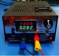
This is a very nice kit, other than it should have come with a Heat-sink and a fan. It has a spot for a fan voltage regulator that is handy for driving a Digital Volt & Current Meter (red/blue display). I swapped it out the CT7824 for a CT7812 (12volt reg) to drive a DVM and a 40x40mm 12v fan used on many 3D Printers. Get a Big Heat-sink and a fan for this kit. The kit did come with one set of connectors to remote mount one of the variable resistors because they are too close on the PCB. Instructions were easy to download and understand. Heat-sink can be tapped #6-32 or M3 for the transistor and mounting to the PCB. Using DVM from above review.(Geekcreit DVAM)


The best DIY for amateur use. There is a lot of material on the internet for help. And with the addition of an old transformer we have a linear power supply for light and basic use !!!!! Το καλύτερο DIY για ερασιτεχνική χρήση. Υπάρχει πάρα πολύ υλικό και στο internet για βοήθεια. Και με την προσθήκη ενός παλιού μετασχηματιστή έχουμε ένα γραμμικό τροφοδοτικό για ελαφριά και βασική χρήση!!!!!

Great power supply with good values Easy to solder good quality Good price I'm very happy with this product I recommend this product


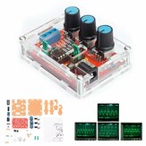
Geekcreit® XR2206 Function Signal Generator DIY Kit Sine Triangle Square Output 1HZ-1MHZ
DC5V-9V LED Chaserr DIY Kit LED Tracking Light DIY Parts Electronic Production Kit
Geekcreit® DIY Shaking LED Dice Kit With Small Vibration Motor
Geekcreit® DIY Radio Electronic Kit Parts 51 Single-chip FM Digital Sound Machine
3Pcs Original Hiland 0-30V 2mA - 3A Adjustable DC Regulated Power Supply Module DIY Kit

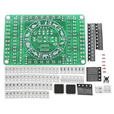
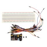
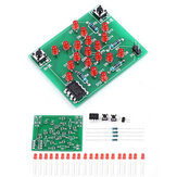
5Pcs DIY SMD Rotating LED SMD Components Soldering Practice Board Skill Training Kit
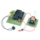
Geekcreit® DIY Mini Tesla Coil Module Unassembled 15W DC 15-24V 2A Plasma Speaker Electronic Kit

EQKIT® DIY FLA-1 Simple Flashlight Circuit Board Electronic Kit


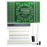
TJ0161 400-hole Starter Kit Resistor LED Capacitor Jumper Wires Breadboard Resistor Kit for UNOR3
Geekcreit® DS3231 High Accuracy Multifunction LED Dot Matrix Animation Effects Clock DIY Kit
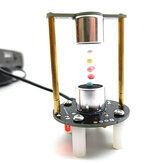
DIY Ultrasonic Suspension Learning Kit Mini Levitator Set 12V Not Assembly
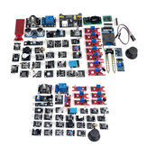
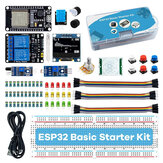
45 IN 1/37 IN 1 Sensor Module Starter Kits Set For Arduino Raspberry Pi Education Bag Package
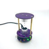
DC12V DIY Electronics Kit Ultrasonic Suspension Standing Wave Controller Diy Welding Kit
DIY LED Digital Watch Electronic Clock Kit With Transparent Cover
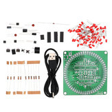
DIY Dream Crystal Electronic Column Light Cube LED Music Voice Spectrum Kit
DIY 51 Single Chip Microcomputer Electronic Scale Production Kit

Tri-color/Colorful Curved-leaf Christmas Tree Standard/Music Version DIY Electronic Kits

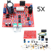
5Pcs Original Hiland 0-30V 2mA - 3A Adjustable DC Regulated Power Supply DIY Kit
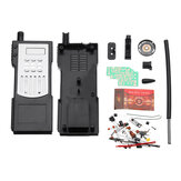
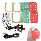
DIY Electronic Walkie-talkie Production Kit Starter Kits Welding Experiment Training Kit

Geekcreit® DIY Mini Tesla Coil Module Unassembled 15W DC 15-24V 2A Plasma Speaker Electronic Kit


830-hole Breadboard for UN0 R3 Starter Kit with Mainboard DIY Electronic Kits
EQKIT® Arc Ignition Lighter DC3-5V 3A DIY High Pressure Electronic Lighter Module Kit

EQKIT® 60 Seconds Electronic Timer Kit DIY Parts Soldering Practice Board

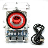
EQKIT® FM Stereo Radio Kit 76-108Mhz Frequency 180mAh 32Ω Impedance YFM-1 DIY Electronic Parts

Starter Kit for UN0 R3 Beginner 13 in 1 Starter Kit Mini Breadboard LED Light Jumper Wire Button

EQKIT CNC Regulated Power Supply Kit Adjustable with Voltage Indication Electronic DIY Production
Electronic Circuit DIY Production Analog Telegraph DIY Spare Parts Welding Training DIY Kit

100PCS 10 Specifications Car Remote Control Key Touch Switches Buttons Touch Key Component Package