Feature:
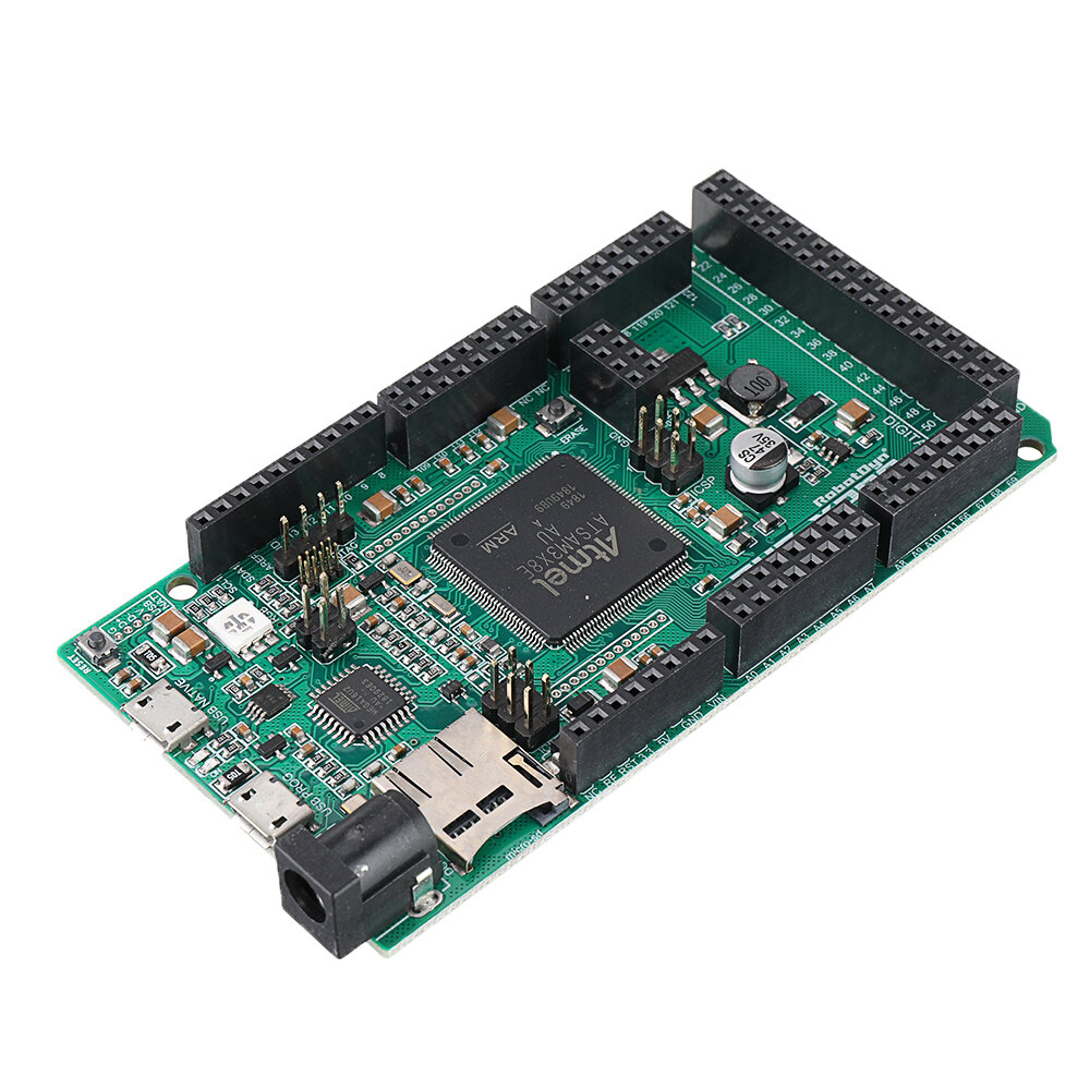
This is a SAM3X8E ARM Cortex-M3 based
microcontroller board. This is one of the few boards, based on the
32-bit ARM core. It is upgraded version of the regular ArduinoDUO board,
it has 98 digital inputs/outputs (that’s 30 more than the original
model), 12 analog inputs, 4 UART (hardware serial ports), 84 MHz clock
frequency, USB OTG connection, 2 DACs (D / A), TWI, power connector, SPI
header, JTAG header, reset button and erase button. Also on board can
find Micro-SD card reader and socket for Wi-Fi module ESP-01.
The controller works on a 3.3V logiclevel. The board has the USB interface, simply connect it to your
computer with a micro-USB cable, or connect it with an AC adapter or
battery to start working with it. RobotDyn DUE XPRO is compatible with
allArduino supported devices.
IOREF:
Allows the attached display with the
correct configuration to adapt to the voltage provided by the board.
This ensures that the screen is compatible with a 3.3V board, such as
the Due and AVR boards, which operate at 5 V.
Power:
RobotDyn DUEXPRO can be powered by a USB
connector or from an external power source. The power source is selected
automatically. External (non-USB) power can be supplied either from the
AC adapter to the direct current or from the battery. The adapter can
be connected by inserting a 2.1 mm center-positive plug into the card's
power connector. Battery pins can be plugged into the GND and VIN pins
of the POWER connector. The board can operate from an external power
source from 6 to 20 volts, the recommended range is 7 to 12 volts. Power
pins are as follows:
VIN - The input voltage on the
Arduinoboard when using an external power supply (as opposed to 5 volts
from a USB connection). You can power the board through this contact, or
access it if you power it via USB cable.
5V - This pin output provides a 5V
current to the board with the help of adjustable voltage regulator. The
board can be powered from a DC power connector (7–12V), a USB connector
(5V), or a VIN pin on the board (7–12V). Applying voltage through the 5 V
or 3.3 V pins bypasses the regulator, so make sure that the voltage is
stable and within the acceptable range.
3V - Power supply 3.3 V from the built-in
regulator. The maximum current consumption is 800 mA. This controller
also provides power to the SAM3X microcontroller.
GND – Ground pins.
IOREF - This pin on the DUEXPRO board
provides the reference source with which the microcontroller operates. A
properly configured screen can read the voltage on the IOREF contact
and select the appropriate power source or turn on the voltage
converters at the outputs, to operate on 5V or 3.3V.
Memory:
SAM3X has 512 KB (2 blocks of 256 KB) of
flash memory for storing code. The board comes with a bootloader already
pre-burned. Available SRAM is 96 KB in two adjacent banks of 64 KB and
32 KB. All available memory (Flash, RAM, and ROM) can be accessed
directly as a single address space. You can erase the SAM3X flash memory
using a built-in erase button. This will remove a currently loaded
thumbnail from the MCU. To wipe the memory, press and hold the "Erase"
button for a few seconds while the board is on.
Inputs and outputs:
Digital I / O: Total 98. Each of the 98
digital pins on DUEXPRO can be used as an input or output using the
pinMode (), digitalWrite () and digitalRead () functions. They operate
at 3.3V logiclevel. Each output can provide a current of 3 mA or 15 mA,
or consume a current of 6 mA or 9 mA, depending on the output. They
also have an internal pull-up resistor (disabled by default) at 100 kΩ.
In addition, some contacts have specialized functions:
Serial: 0 (RX) and 1 (TX)
Serial 1: 19 (RX) and 18 (TX)
Serial 2: 17 (RX) and 16 (TX)
Serial 3: 15 (RX) and 14 (TX)
PWM: pins from 2 to 13 Provide 8-bit PWM
output using the analogWrite () function. PWM resolution can be changed
using the analogWriteResolution () function.
SPI: SPI Header pins support SPI
communication using the SPI library. SPI pins have a central 6-pin
connector that is physically compatible forUno, Leonardo and Mega2560.
The SPI header can only be used to communicate with other SPI devices,
and not for SAM3X programming using In-Circuit-Serial-Programming
technology.
CAN: CANRX and CANTX pins support the CAN communication protocol.
I2C TWI 1: 20 (SDA) and 21 (SCL)
I2C TWI 2: SDA1 and SCL1 Support TWI
communication using the Wire library. SDA1 and SCL1 can be controlled
using the Wire1 class provided by the Wire library. While SDA and SCL
have internal pull-up resistors, SDA1 and SCL1 do not. Adding two
pull-up resistors on the SDA1 and SCL1 lines is required to use Wire1.
Analog inputs: contacts from A0 to A11.
Due has 12 analog inputs, each of which can provide 12-bit resolution
(that is, 4096 different values). By default, the resolution of the
readings is set to 10 bits for compatibility with other Arduinoboards.
You can change the resolution of the ADC using the ReadResolution ().
Applying a voltage of more than 3.3 V to the contacts DUEXPRO might
damage the SAM3X chip. The AnalogReference () function is ignored in
DUEXPRO. The AREF pin is connected to the SAM3X analog reference pin
through a bridge resistor. To use the AREF pin, resistor BR1 must be
disconnected from the board.
DAC1 and DAC2: These pins provide true
analog outputs with 12-bit resolution (4096 levels) with the analogWrite
() function. They can be used to create audio output using an audio
library. Please note that the output range of the DAC is actually only
from 0.55 V to 2.75 V. Other pins on the board: AREF Reference voltage
for analog inputs. Used with AnalogReference ().
Reset: Set this line LOW to reset the
microcontroller. Typically used to add a reset button to shields that
block a button on the board.
Communication:
The RobotDyn DUE XPRO has a number of
means for communicating with a computer, another Arduinoboard or other
microcontrollers, as well as various devices, such as phones, tablets,
cameras, etc. The SAM3X provides one hardware UART and three hardware
USART for TTL serial communication.
The programming port is connected to the
ATmega16U2, which provides a virtual COM port for software on the
connected computer (Windows will need an .inf file to recognize the
device, but OSX and Linux machines automatically recognize the board as a
COM port). The 16U2 is also connected to the hardware UART SAM3X. A
serial connection on the RX0 and TX0 pins provides communication between
the serial port and USB, for programming the board through the
ATmega16U2 microcontroller. The Arduinosoftware includes a serial
monitor that allows you to send simple text data to and from the board.
The RX and TX indicators on the board will flash when transmitting data
through an ATmega16U2 chip and a USB connection to a computer.
The USB port is connected to the SAM3X,
it allows for serial communication via USB. This provides a serial
connection to the Serial Monitor or other applications on your computer,
and will also allow to emulate a USB mouse or keyboard to a connected
computer.
The Native USB port can also act as a
USB host for connected peripherals, such as mice, keyboards, and
smartphones. To use these features, see the USBHost man pages.
SAM3X also supports TWI and SPI
communication. The Arduinosoftware includes the Wire library to simplify
the use of the TWI bus. For SPI communication, use the SPI library.
Programming:
DUEXPRO can be programmed using the
ArduinoIDE. Uploading thumbnails to the SAM3X is different from AVR
microcontrollers, which can be found on other Arduinoboards, since flash
memory must be erased before being programmed again. The boot to the
microcircuit is controlled by a ROM on the SAM3X, which is started only
when the flash memory of the chip is empty. Any of the USB ports can be
used to program the board, although it is recommended to use the
programming port due to the way the chip is erased.
Programming Port: To use this port,
select “ArduinoDue (ProgrammingPort)†as the board in the ArduinoIDE
“Tools†menu. Connect the DUEXPRO programming port (closest to the DC
power connector) to your computer. The programming port uses 16U2 as a
USB-to-serial chip connected to the first SAM3X UART (RX0 and TX0). The
16U2 has two pins connected to the SAM3X reset and erase contacts.
Opening and closing a programming port connected at 1200 bps starts the
“hard erase†procedure for the SAM3X chip, activating the erase and
reset contacts on the SAM3X before establishing a connection with the
UART. This is the recommended programming port. This is more reliable
than the “soft erase†that occurs on its own port, and it should work
even if the main MCU fails.
Own port: to use this port, select
“ArduinoDue (NativeUSBPort)†as the board in the ArduinoIDE. The native
USB port is connected directly to the SAM3X. Connect your own USB port
Due (closest to the reset button) to the computer. Opening and closing
your own port at 1200 bps starts the “soft erase†procedure: the flash
memory is erased and the board reboots with the bootloader.
Unlike other Arduinoboards that use
avrdude for download, DUEXPRO relies on the bossac. The ATmega16U2
firmware source code is available in the Arduinorepository. You can use
the ISP header with an external programmer (overwriting the DFU
bootloader). Protection against overcurrent via USB RobotDyn DUEXPRO has
a reloadable polyfuse that protects your computer's USB ports against
short circuits and overloads. Although most computers provide their own
internal protection, the fuse provides an extra level of protection. If
more than 500 mA is connected to the USB port, the fuse will
automatically break the connection until the short circuit or overload
is removed. Three screw holes allow you to attach the board to the
surface or housing. Note that the distance between digital pins 7 and 8
is 160 mil (0.16 inch), which is not a multiple of 100 mil from other
pins. RobotDyn DUEXPRO is designed to be compatible with most screens
designed forUno, Diecimila or In connection with this digital pins 0–13
(and adjacent pins AREF and GND), analog inputs 0–5, the power header
and the ICSP header (SPI) are in equivalent places. Further, the main
UART (serial port) is located on the same pins (0 and 1).
Documents:
Package includes:
1 x Development Board